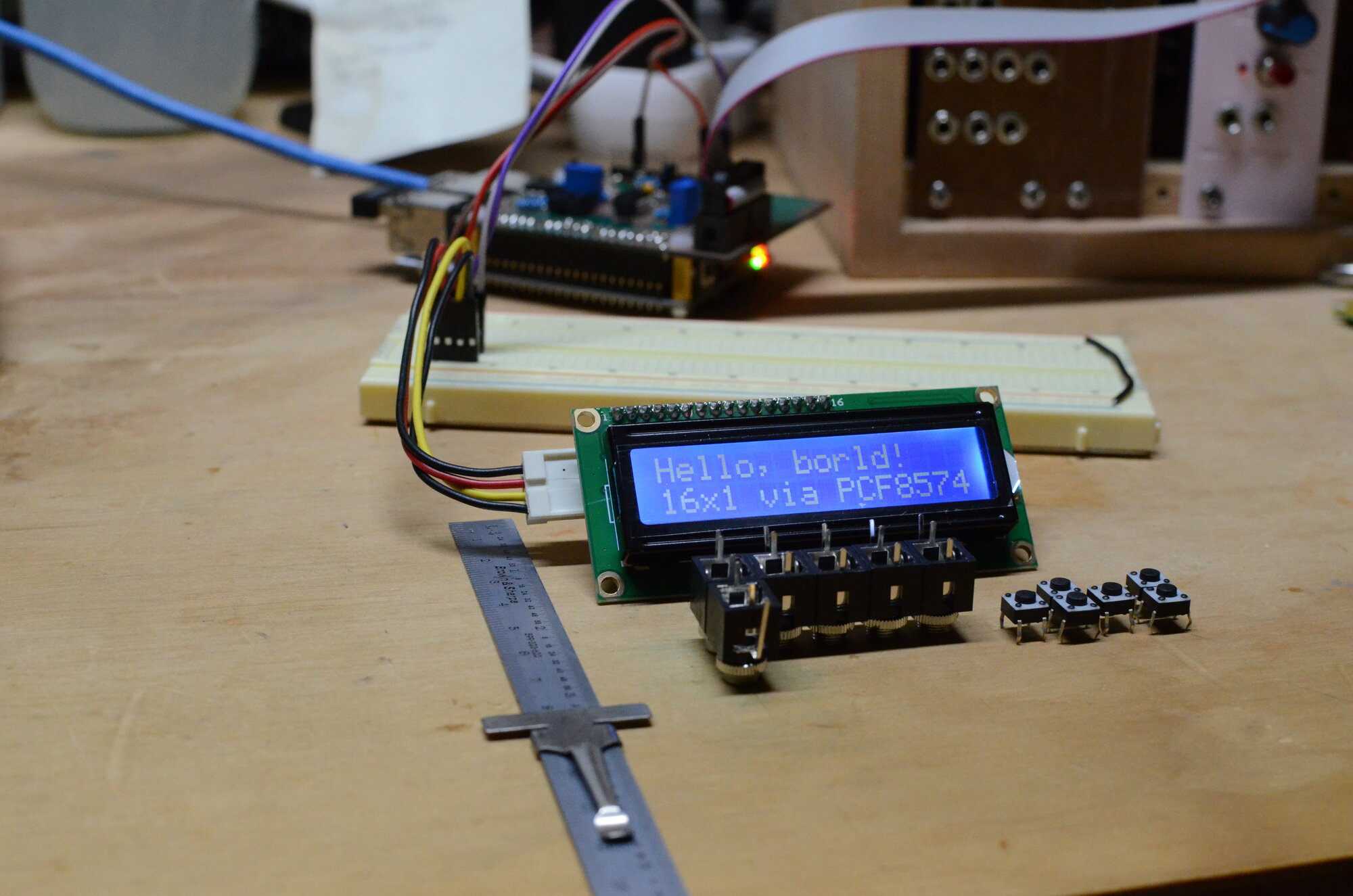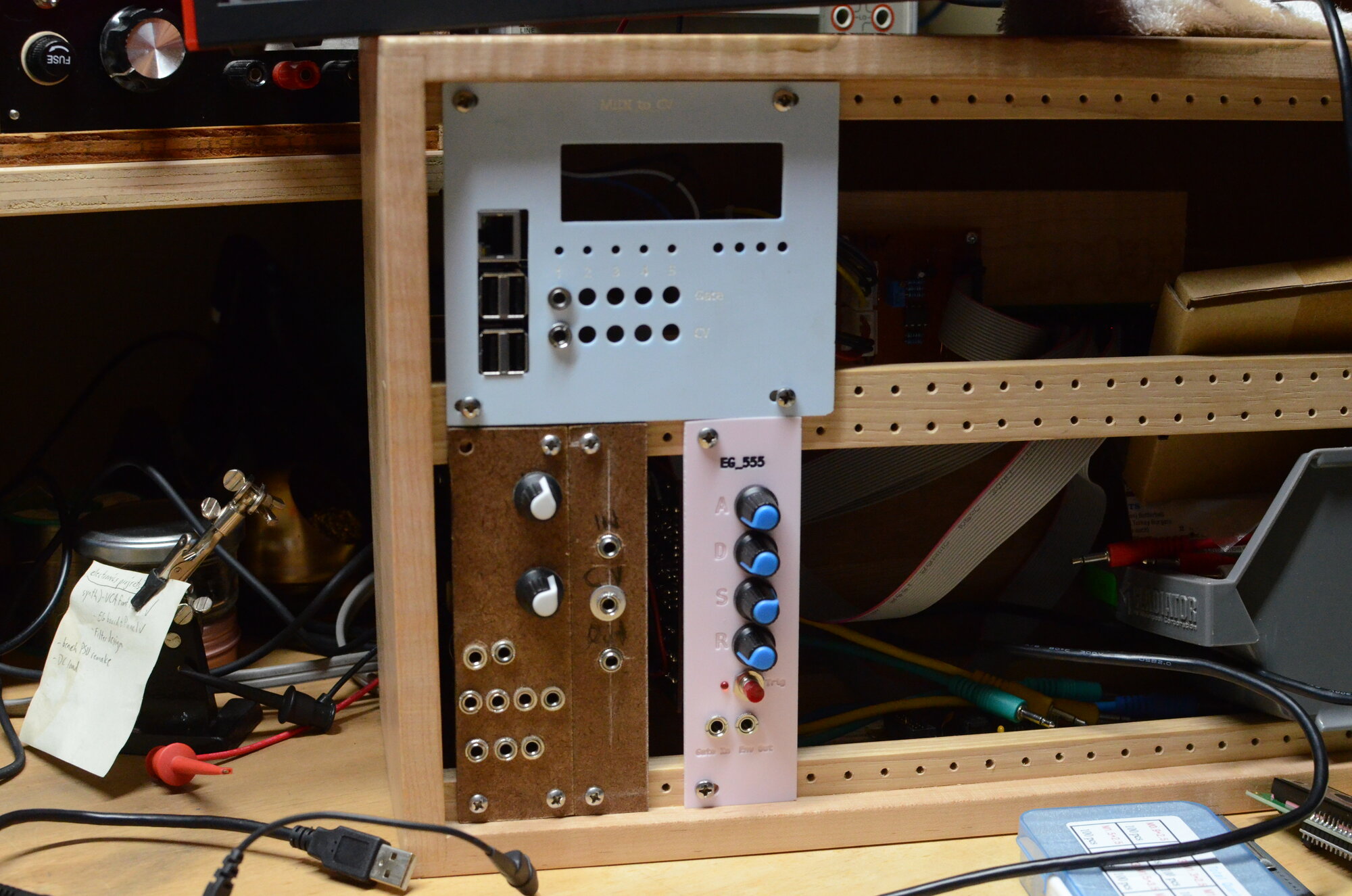
After the last post, we were left with a working voltage controlled oscillator (VCO), voltage controlled amplifier (VCA), and an envelope generator. The next logical step would probably have been to make a voltage controlled filter (VCF) module. I didn't do that. Instead, with most of a working synth 'voice', I wanted to make this thing play music.
This was actually one of the first things I worked on when starting this hobby... 3 years ago? Wow, my investors are going to be pissed.
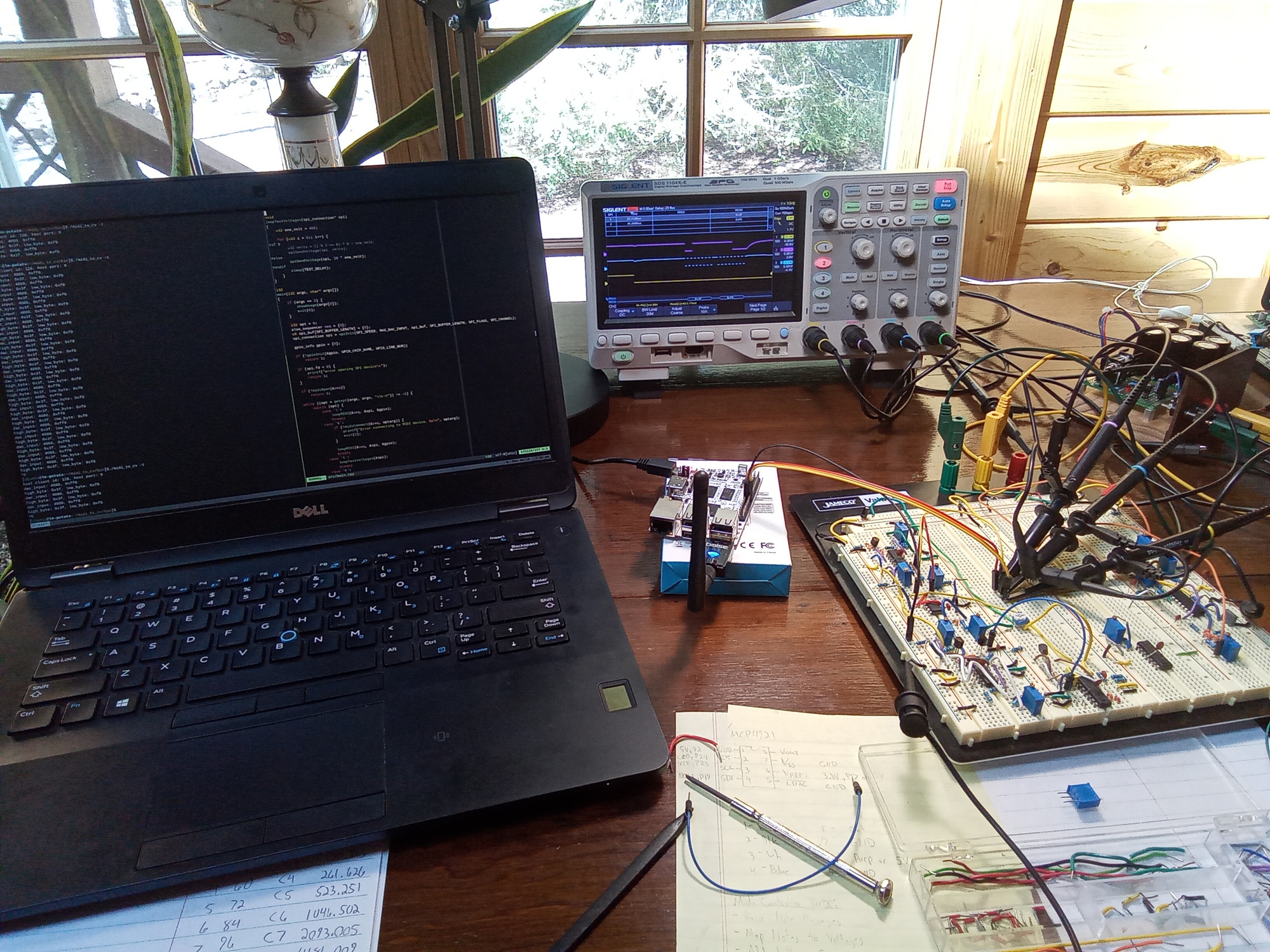
The classic way of generating melodies for analog synthesizers would be an analog sequencer or an instrument that directly outputs voltage and gate signals. That's a little limiting today, especially since I want to focus more on the electronic design and mechanical construction.
For maximum flexibility, and compatibility with modern instruments, a MIDI interface from an actual computer that can output control voltages (CV) and gate signals is ideal. Then we can use things like MIDI controllers and MIDI files to drive the analog voice of the synth. This could be done a little more cheaply with a microcontroller, but you'd lose compatibility with OS MIDI libraries like the ALSA sequencer interface, existing device drivers, and better programming language support. We'll go into more detail about the software in another post.
Mainboard
Before the current RAMpocalypse, but during the previous Covid chip shortages, the Libre Computer single board computers (SBC)s were a good alternative to the more popular Raspberry Pi boards that were unavailable to consumers. I've continued using these over the Raspberry Pi boards because they do a much better job upstreaming their changes to the linux kernel than the larger, and more popular Broadcom-based project. Meaning that you can just install and run an installation image from many linux distributions without needing to apply (an often unmaintained) patch set from the manufacturer of the chipset/SoC.
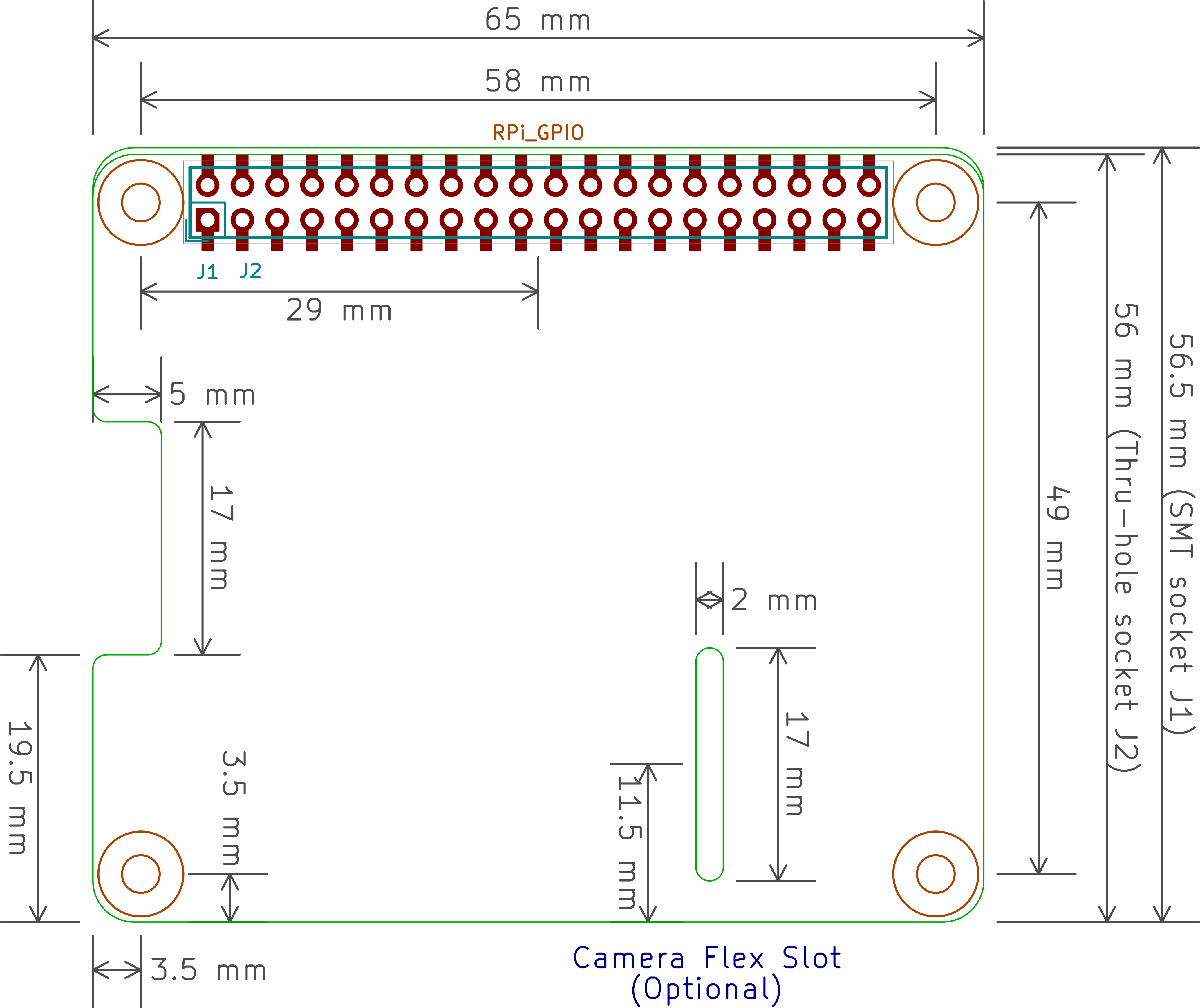
For this project, I'm using the le-potato board from Libre Computer. It has the same form factor as the Raspberry Pi, which means we can use existing 'HATs', and PCB templates.
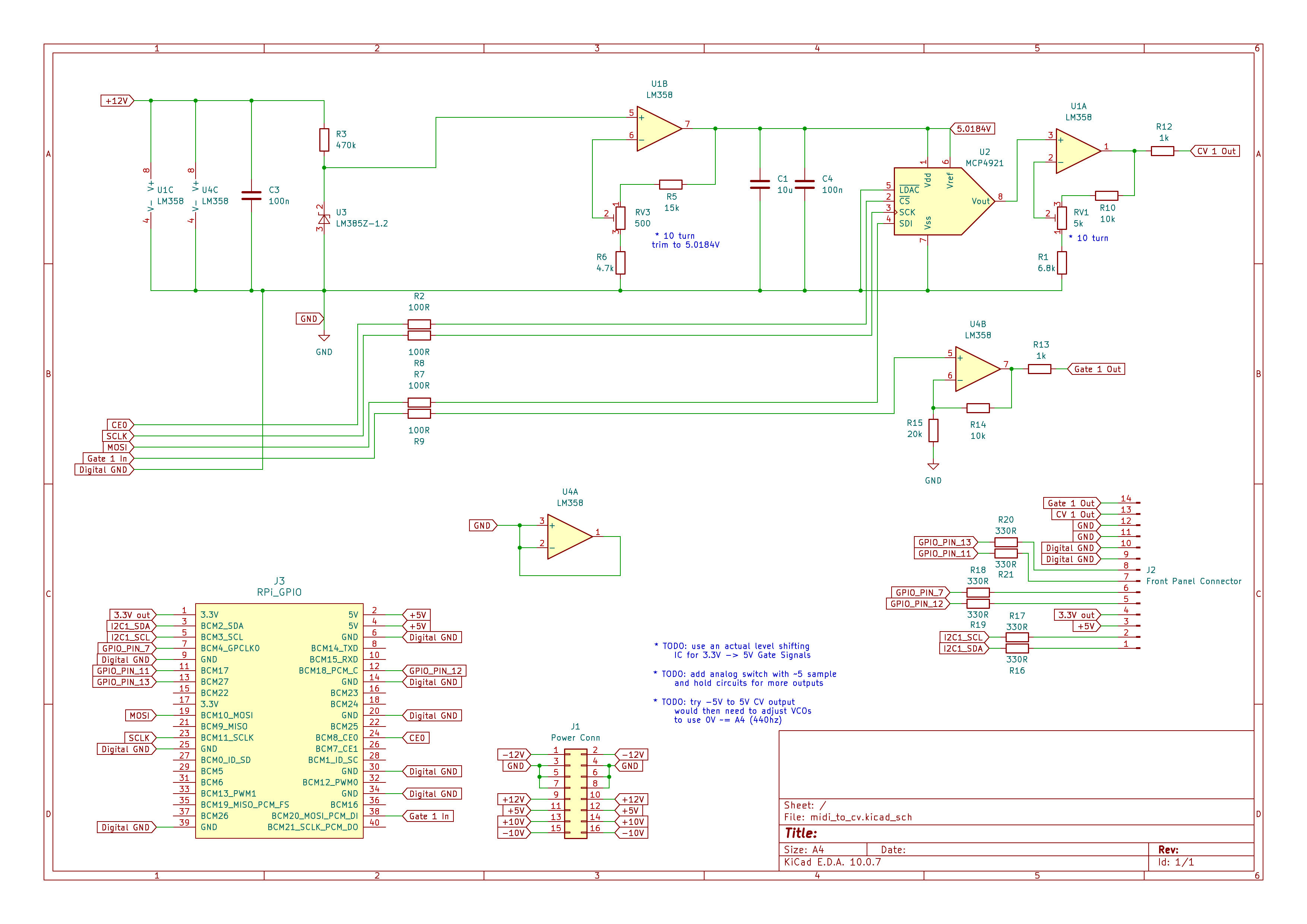
For the prototype, we're using a single MCP4921 digital to analog converter (DAC) and an op-amp circuit to level shift the gate signal from the board's 3.3V digital IO to the expected 0-5V gate on/off. The MCP4921 is a 12-bit DAC, which means we have 4096 discrete steps at the output. If we set the DAC reference voltage to ~5.018V, we can get a DAC output of 5V with a digital input value of 4080. This is cleanly divisilbe by (5 * 12) = 60. That's 5 octaves at 1V/octave, and 12 semitones per octave at 83mV per step. 4080 is also divisible by (10 * 12) = 120, 10 octaves at 0.5V/octave, almost the full 128 note MIDI range, and which can then be level shifted to 0-10V, or -5V-+5V. The prototype uses 0-10V, but -5V-+5V is probably the better option since those are the same levels as the audio signal levels already being passed around (at least now that we learned 10V p-p != -10V - +10V :) ).
The current plan is to add dedicated sample and hold and level shifting ICs for 5 CV/Gate channels in the final module. The DAC settling time is supposedly around 4.5 microseconds, according to the datasheet, which seems fast enough for 5 channels: 4.5 * 5 = 22.5us per channel, and a quarter note at 200BPM is: 1 / (200 * 60 * 4) ~= 20us. That's plenty fast for more reasonable tempos, but another limitation could be the output slew rate of the DAC at 0.55 V/us, and the unknowns from the sample hold and level shifting circuits.
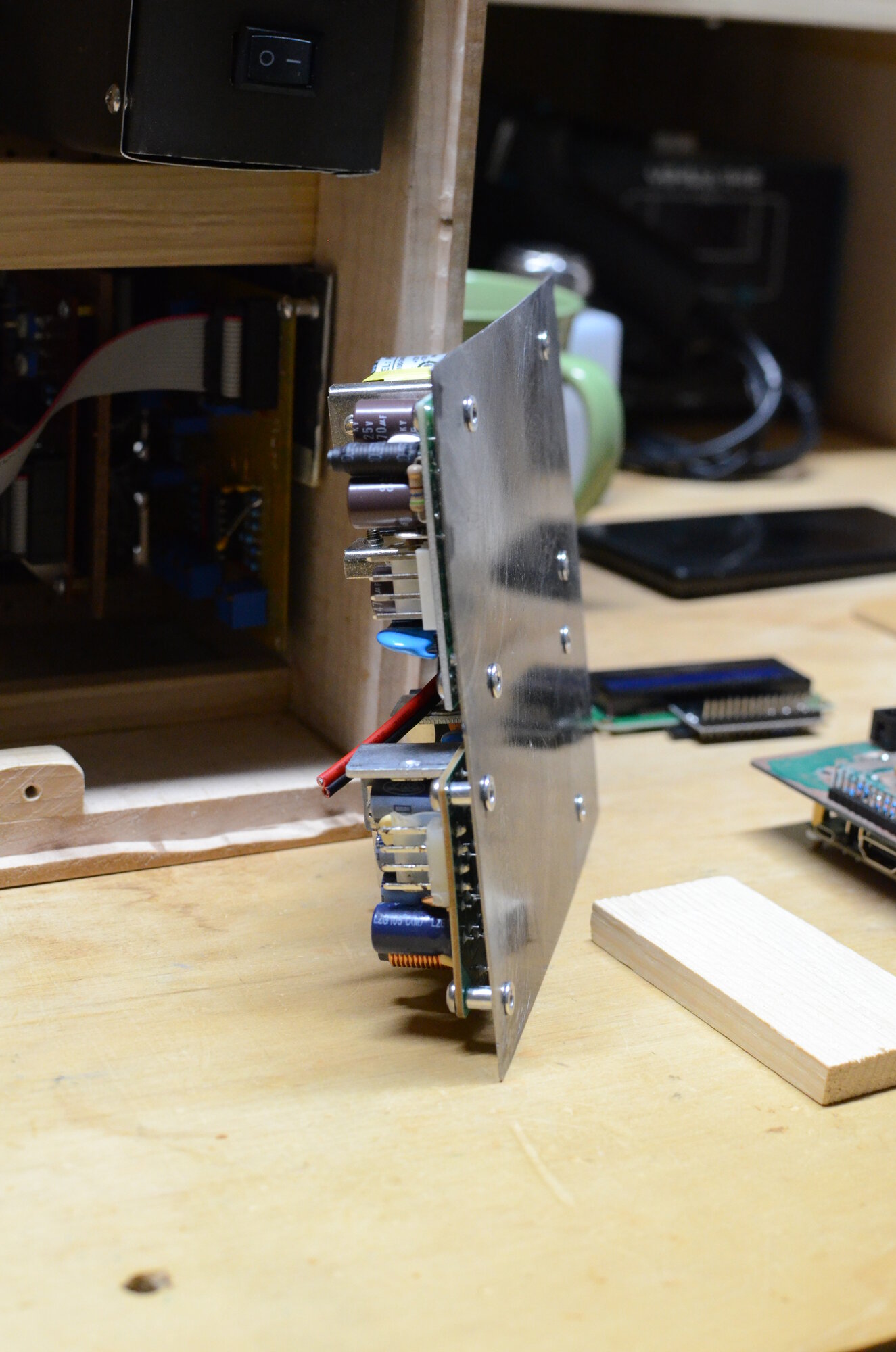
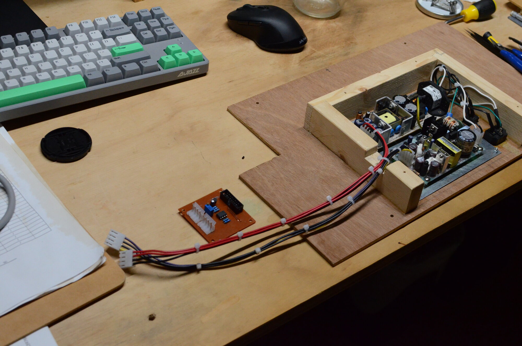
While breadboarding the circuit for the mainboard, I powered the SBC with its own dedicated power supply. The recommended supply from Libre Computer is at least 3A at 5V, which was going to be way too much from what was basically a reference voltage buffered by an op-amp. After verifying that the 5V pin on the le-potato GPIO connector fed into the input side of the polyfuse/input protection circuit, I milled and assembled the prototype mainboard, and added a second switching supply with a new power breakout board.
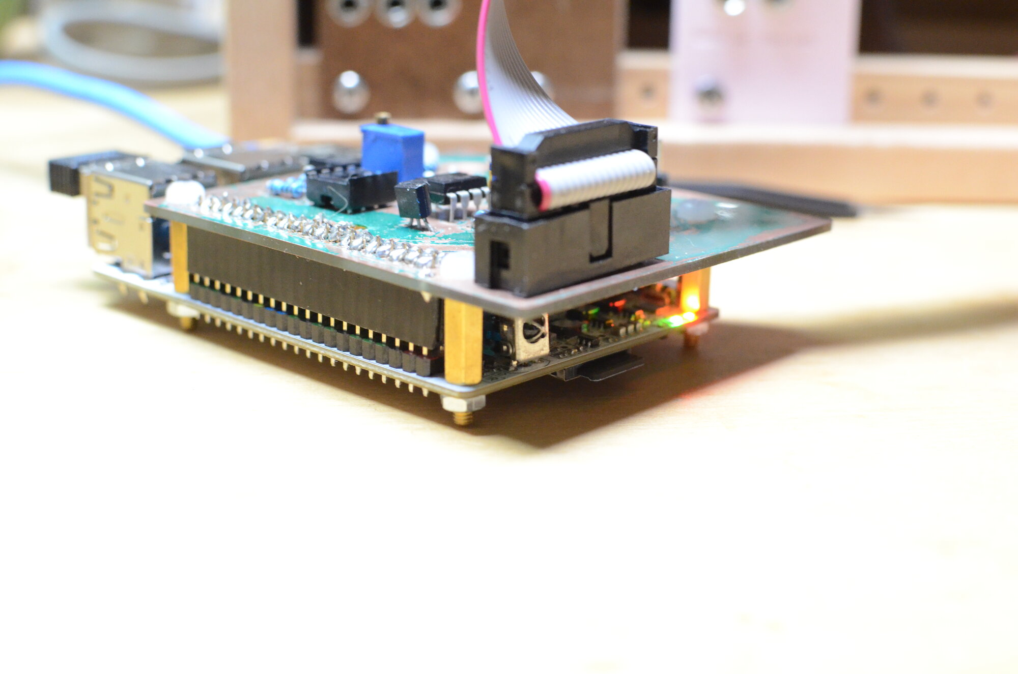
You can see in the last image that the 40 pin female connector doesn't seat all the way flush with the GPIO connector. The system on a chip (SoC) has a heatsink which needs about 12mm of clearance. Past me had already bought some M3 12.5mm standoffs. The electrical connections seem ok so far, but it looks a little janky. I guess it does match the rest of the synth though. I also spent awhile debugging a loose connection on the 8 pin DIP chip that's standing off too high from the board.
The original breadboard circuit had a 100 ohm resistor separating the analog and digital grounds, but that wasn't going to be possible with a single power connector and up to 3A flowing on the 5V circuit. Ideally we'd have a separate supply and return for the high current, digital circuit and the rest of the analog synth, but that's not really possible without changing the power connectors. There's also ocassionaly small signals that could be affected by the ground fluctuations like the VCA differential amplifier input, or the ~41mV steps on the DAC output. So far, I've been able to play music from the board through the synth voice without noticing any effects, but we'll have to keep it in mind in the future, and possibly re-re-design the power supplies.
Some final notes on things I learned from the prototype mainboard: We need to break out the connector for the le-potato UART. It's a pain the remove the mainboard/HAT, and the serial connection is useful for debugging. The front panel will need either 5 more outputs for each channel's gate LED, or (more likely) 5 LED driver transistors on the front panel board. If we want to make the board fit in the dimensions of the SBC, without overhanging, I think it will be neccesary to move to surface mount components. I already had to scrap the overvoltage protection diodes on the SPI connection to the DAC. It also could make sense to use an IO expander chip for some extra front panel controls.